|
|
|
| |
*
호이스트 체인 |
| |
| |
 |
| Excerpt
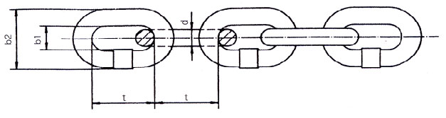
from DIN 5684(Table 1) |
Nominal
diameter |
Pitch |
Width |
Measuring
length 11xt* |
Weight
~Kg/m |
d |
perm.tol. |
t |
perm.tol. |
b1
min. |
b2
max. |
. |
perm.tol. |
4 |
±0.2 |
12 |
+0.15 |
-0.1 |
5 |
13.7 |
132 |
+0.4 |
-0.2 |
0.35 |
5 |
±0.2 |
15 |
+0.2 |
-0.1 |
6 |
16.9 |
165 |
+0.5 |
-0.3 |
0.54 |
(5) |
±0.2 |
(18.5) |
+0.25 |
-0.1 |
6 |
16.9 |
203.5 |
+0.7 |
-0.3 |
0.5 |
6 |
±0.2 |
18 |
+0.25 |
-0.1 |
7.2 |
20.2 |
198 |
+0.6 |
-0.3 |
0.8 |
(6) |
±0.2 |
(18.5) |
+0.25 |
-0.1 |
7.2 |
20.2 |
203.5 |
+0.7 |
-0.3 |
0.8 |
7 |
±0.3 |
21 |
+0.3 |
-0.15 |
8.4 |
23.6 |
231 |
+0.7 |
-0.4 |
1.1 |
(7) |
±0.3 |
(22) |
+0.3 |
-0.15 |
8.4 |
23.6 |
242 |
+0.8 |
-0.3 |
1.1 |
8 |
±0.3 |
24 |
+0.3 |
-0.15 |
9.6 |
27 |
264 |
+0.8 |
-0.4 |
1.4 |
9 |
±0.4 |
27 |
+0.35 |
-0.2 |
10.8 |
30.4 |
297 |
+1 |
-0.5 |
1.8 |
10 |
±0.4 |
28 |
+0.35 |
-0.2 |
12 |
34 |
308 |
+1 |
-0.5 |
2.2 |
11 |
±0.4 |
31 |
+0.4 |
-0.2 |
13.2 |
37.4 |
341 |
+1.1 |
-0.5 |
2.7 |
13 |
±0.5 |
36 |
+0.45 |
-0.25 |
15.6 |
44.2 |
396 |
+1.3 |
-0.6 |
3.8 |
14 |
±0.6 |
41 |
+0.5 |
-0.3 |
16.8 |
47.6 |
451 |
+1.4 |
-0.7 |
4.4 |
16 |
±0.6 |
45 |
+0.6 |
-0.3 |
19.2 |
54.4 |
495 |
+1.6 |
-0.8 |
5.7 |
18 |
±0.9 |
50 |
+0.65 |
-0.3 |
21.6 |
61.2 |
550 |
+1.8 |
-0.9 |
7.3 |
20 |
±1 |
60 |
+0.8 |
-0.4 |
24 |
68 |
660 |
+2 |
-1 |
8.8 |
22 |
±1.1 |
66 |
+0.85 |
-0.45 |
26.4 |
75 |
726 |
+2.4 |
-1.1 |
10.7 |
|
| |
* All
values in brackets are to be avoided
for new production. |
| |
Other dimension
(ISO, JIS or customer standard...) upon
request. |
| |
* Please supply a chain
wheel in order to ensure smooth operatio
of chain and wheel. |
| |
신규발주품의 경우
괄호안의 수치는 적용되지 않음. |
| |
* ISO, JIS 혹은 특수 사양 관련
체인의 주문시 체인과 체인휠의 원활한 작동을 위해 로드 쉬브를 제공
해주기 바람. |
|
| |
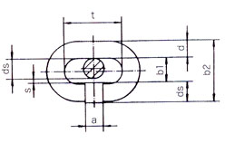
| Nominal diameter
d |
up to 9 |
over 9 |
| Inside width b1
min. |
1.2 d |
1.2 d |
| Welded leg ds max.
|
1.075 d |
1.075 d |
| Unwelded leg d |
1 d |
1 d |
| Manufacturing tolerance
|
0.1 d |
0.125 d |
| Outside width b2
max. |
3.375 d |
3.4 d |
* To guarantee non-kinking
of the chain, a minimum
clearance s=0.125 d a must be
kept between the
welds
on connected links.
|
|
 |
|
|
| |
| R80 수동 호이스트전용체인 |
Denomination |
. |
PEWAG
HEO-G80 |
Stress
at manu
facturing test force |
. |
. |
FP
min |
N/mm2
|
500 |
Breaking
stress |
B
min |
N/mm |
800 |
Breaking
elongation |
A
min |
% |
10 |
Minimum
surface hardness on any
part of tde chain ink |
. |
. |
d<7mm |
HV
5 |
380 |
D
7mm |
HV
10 |
Driving
system
of hoist |
. |
motor
operated |
hand
operated |
Duty
rating group |
. |
light
1 Bm |
1Dm |
Permissible
stress
at working load limit |
. |
160 |
200 |
tr |
N/mm |
Limiting
stress |
N/mm |
200 |
300 |
Shock
factor |
. |
1.25 |
1.5 |
Material |
. |
nickel-molybdenum
special alloy steel |
Ratio
of working load limit to manu-facturing
test force to breaking force |
1:3,
15: 5 |
1:2,
5:4 |
. |
. |
. |
max.
working
load
limit |
max.
working
load
limit |
Manu-
facturing test force |
Breaking
force |
Duty
rating group |
1Bm |
1Dm |
. |
. |
Nominal
diameter |
FTr |
FTr |
FP
min |
FB
min |
d[mm] |
[kg] |
[kg] |
[KN] |
[KN] |
4 |
400 |
500 |
12.5 |
20 |
5 |
630 |
750 |
20 |
32 |
6 |
900 |
1150 |
28 |
45 |
7 |
1250 |
1500 |
40 |
60 |
8 |
1600 |
2000 |
50 |
80 |
9 |
2000 |
2500 |
63 |
100 |
10 |
2500 |
3200 |
80 |
125 |
11 |
3000 |
3750 |
95 |
150 |
13 |
4250 |
5300 |
132 |
212 |
14 |
5000 |
6300 |
150 |
250 |
16 |
6550 |
8200 |
200 |
320 |
18 |
8300 |
10400 |
250 |
400 |
22 |
12400 |
15500 |
400 |
630 |
/ |
|
|
| |
Denomination |
. |
PEWAG
HEO-G80 RAS |
Stress at
manu
facturing test force |
. |
. |
б FP min
|
N / ㎟ |
500 |
Breaking stress |
б B min |
N /㎟ |
800 |
Breaking elongation
|
A min |
% |
10 |
Minimum
surface
hardness in the link intrados
accdg. to Vickers
DIN 50133BL.1 |
. |
. |
d<4.5mm |
HV 5 |
570 |
d>4.5< 7mm |
HV 5 |
580 |
d>7<12mm |
HV 10 |
d>12mm |
HV 10 |
500 |
Case-depth
(link ingrados)
HTA
(macroetching) |
. |
. |
d<10mm |
xd |
0.03+0.01 |
d>10<12mm
d>12mm |
xd |
0.02+0.01 |
Driving system of
hoist |
. |
motor operated
|
Duty rating group
|
. |
heavy
1Am, 2m |
light
1Bm |
permissible
stress
at working load limit |
Tr |
N/mm |
125 |
160 |
. |
Limiting stress |
N/mm |
180 |
200 |
Shock factor |
. |
1.45 |
1.25 |
Material |
. |
nickel-molybdenum
special alloy steel |
Ratio of working load
limit to manu-facturing test force to
breaking force |
1:4,
6:4 |
1:3, 15:5 |
. |
. |
. |
max.
working
load
limit |
max.
working
load
limit |
Manu-
facturing
test
force |
Breaking force |
Duty rating group
|
1Am,2m |
1Bm |
. |
. |
Nominal diameter |
FTr |
FTr |
FP min |
FB min |
d[mm] |
[kg] |
[kg] |
[KN] |
[KN] |
4 |
320 |
400 |
12.5 |
20 |
5 |
500 |
630 |
20 |
32 |
6 |
700 |
900 |
28 |
45 |
7 |
1000 |
1250 |
40 |
60 |
8 |
1300 |
1600 |
50 |
80 |
9 |
1600 |
2000 |
63 |
100 |
10 |
2000 |
2500 |
80 |
125 |
11 |
2500 |
3000 |
95 |
150 |
13 |
3200 |
4250 |
132 |
212 |
14 |
4000 |
5000 |
150 |
250 |
16 |
5000 |
5300 |
200 |
320 |
18 |
6300 |
8000 |
250 |
400 |
22 |
9500 |
12500 |
400 |
630 |
|
| |
|
|
| |
|
| |
|
|
|